|
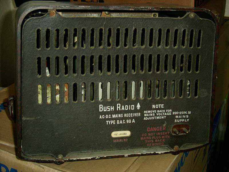
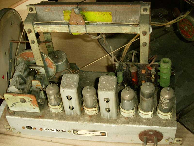
| Rear view |
The back is removed.
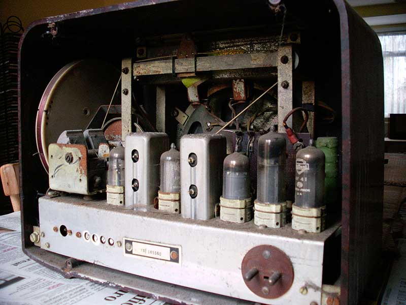
|
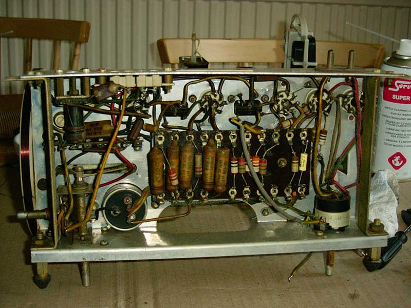
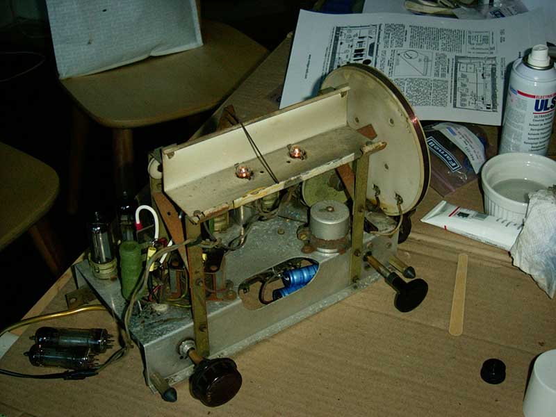
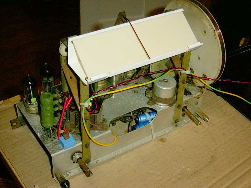
| The first look inside |
|
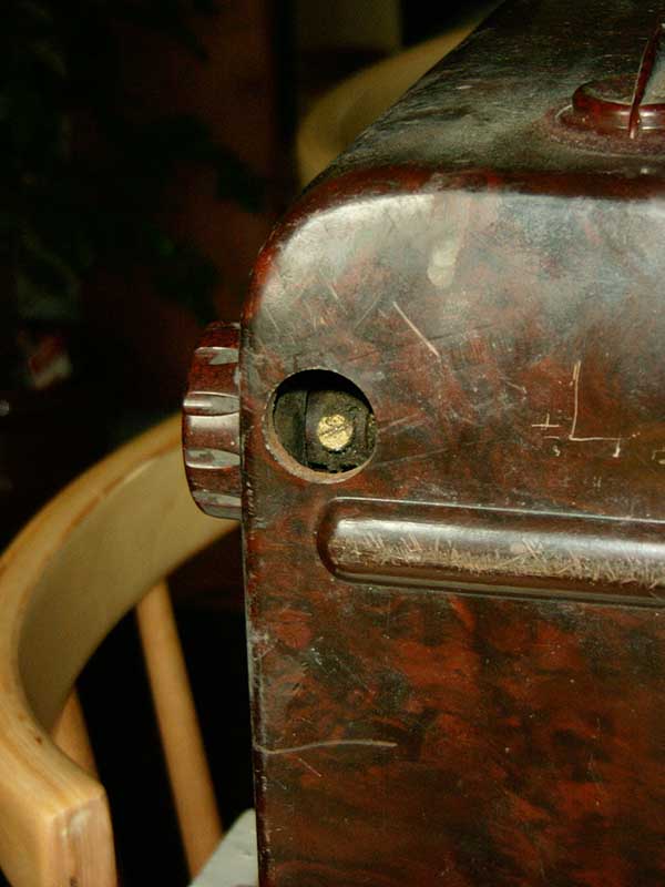
| Access to the knob screw |
The tuning knob is removed, accessing the screw from underneath. Access to the screw holding on the waveband switch knob is from the back of the cabinet.
The volume knob is missing but Colin Boggis of Radio Renaissance is extremely helpful in finding a replacement.
A very kind offer of a replacement is also received from Rob Rusbridge of The Wireless Works.
|
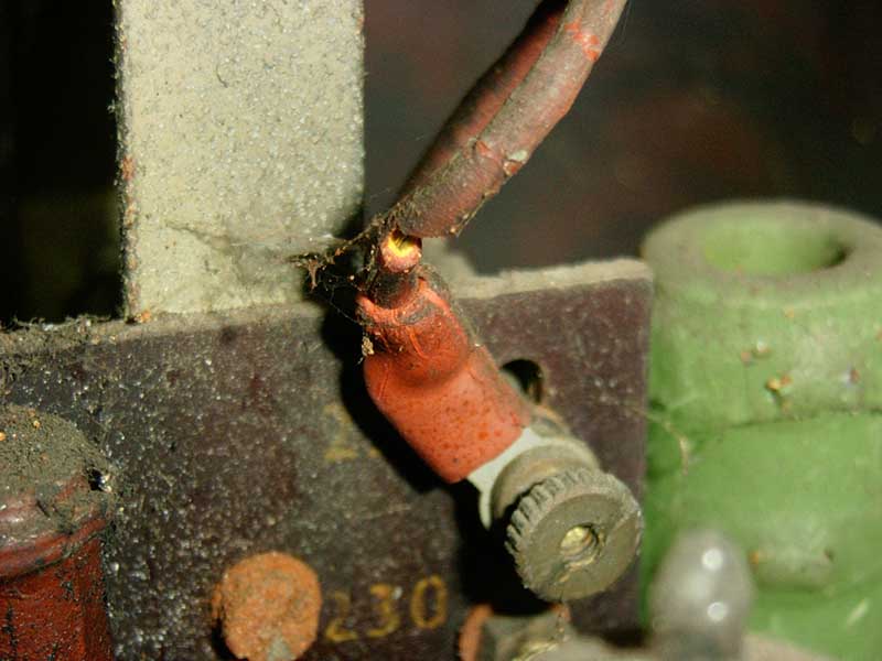
| The capacitor across the mains input is in two pieces |
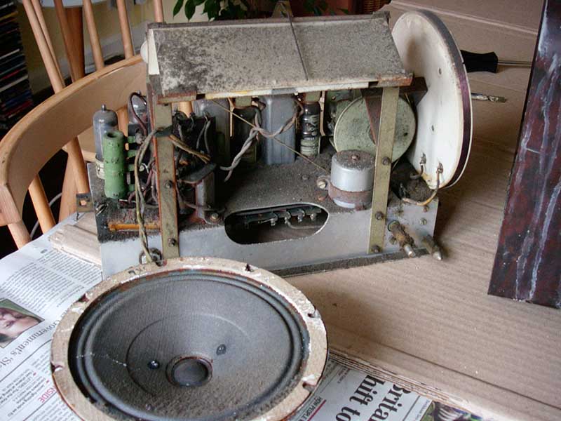
The complete chassis is removed from the cabinet.
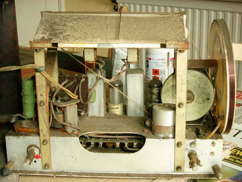
The four brackets fastening the speaker to the front of the cabinet are removed, and the speaker lifted out.
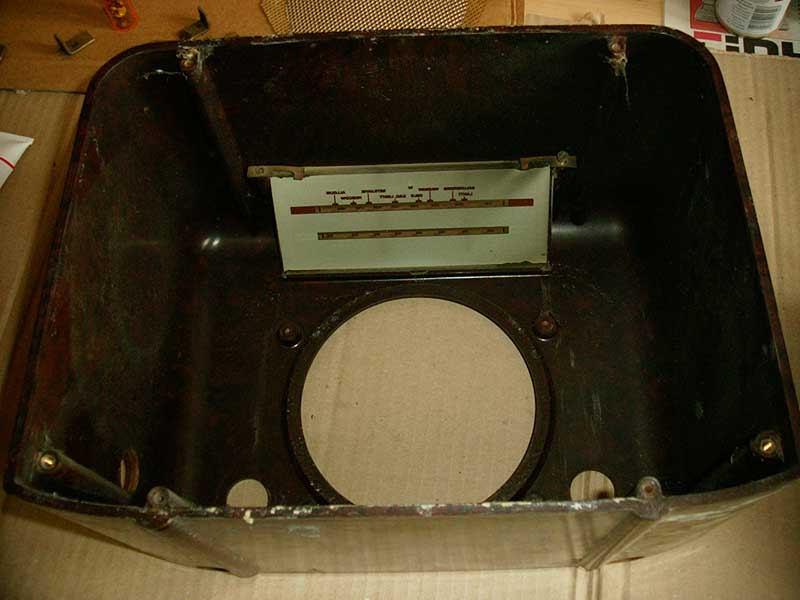
|
| The tuning scale glass in the cabinet |
The tuning scale glass locates in a groove at its lower edge, and is held in place with rubber strips top and bottom, and two clips at the top. The glass is removed.
When the dust is cleared from the back of the glass, some flaking of the lettering is apparent. Using some soapy water to wash the back of the glass causes some further slight damage at one edge. Probably best to merely use a dry paint brush to clear the loose dust.
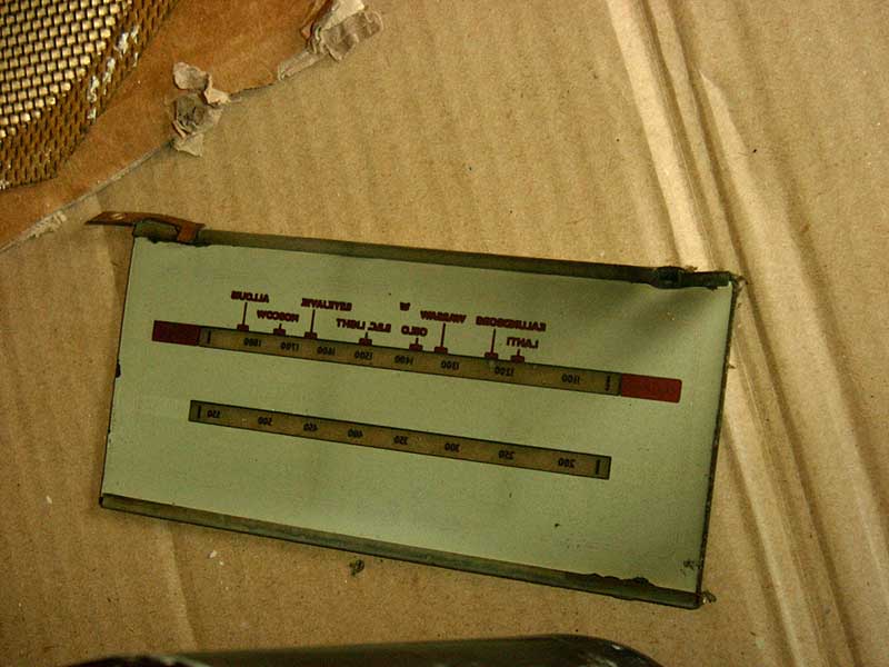
|
| The tuning scale glass removed. The lettering is extremely delicate! |
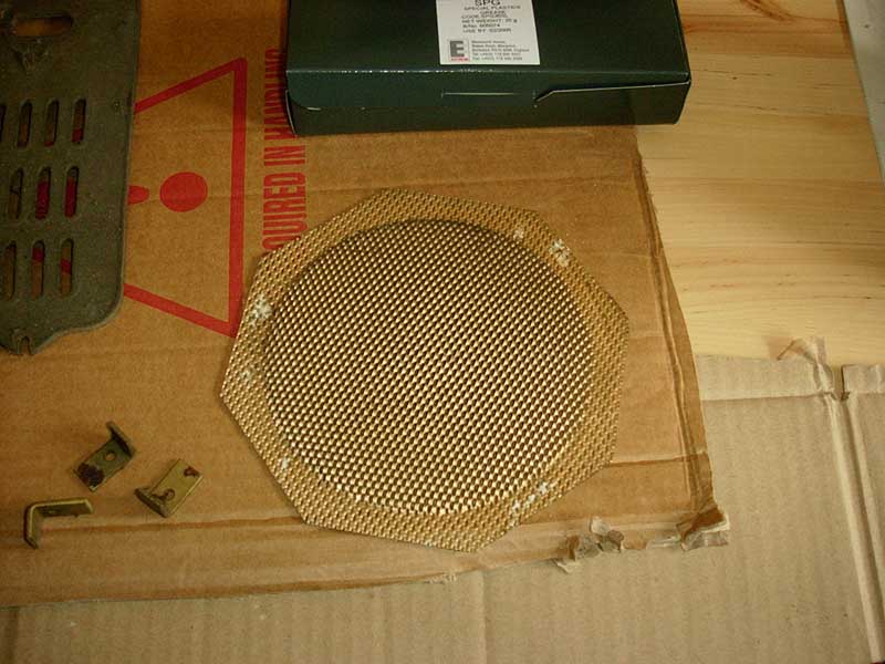
The speaker grille is cleaned with a toothbrush and soapy water. The temptation to spray it gold is resisted, for now.
|
| The speaker grille |
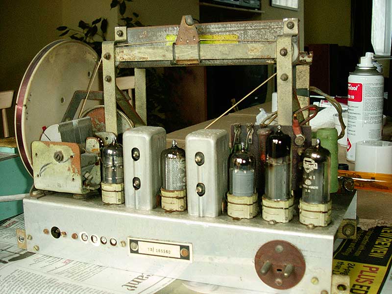
After a lot of work with a vacuum cleaner and toothbrush, most of the dirt is removed from the chassis.
|
| 50 years of grime largely removed |
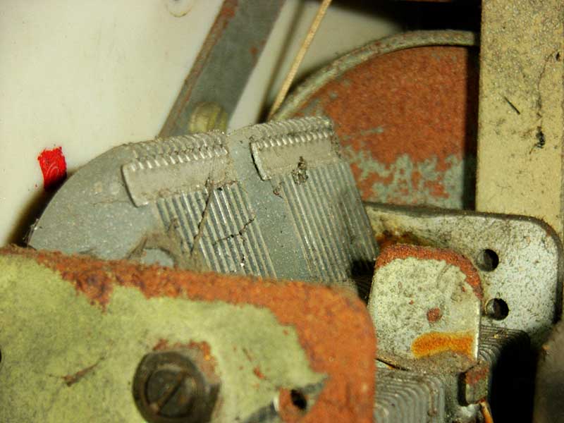
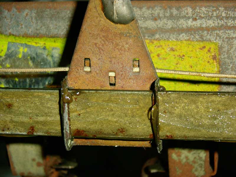
The tuning mechanism is stiff and noisy, but an application of oil and grease soon has it working perfectly.
Before working on the wiring and components, the "Trader" service sheet for the set is obtained - see the link at bottom of the page.
The obvious defective wiring is replaced.
Most of the capacitors are replaced with modern equivalents.
Some temporary components and wiring are fitted, but those near to the dropper resistor are later replaced with parts more suited to the high temperatures: fibre glass insulation is used, and the capacitor across the mains input is replaced with a class X1 device.
|
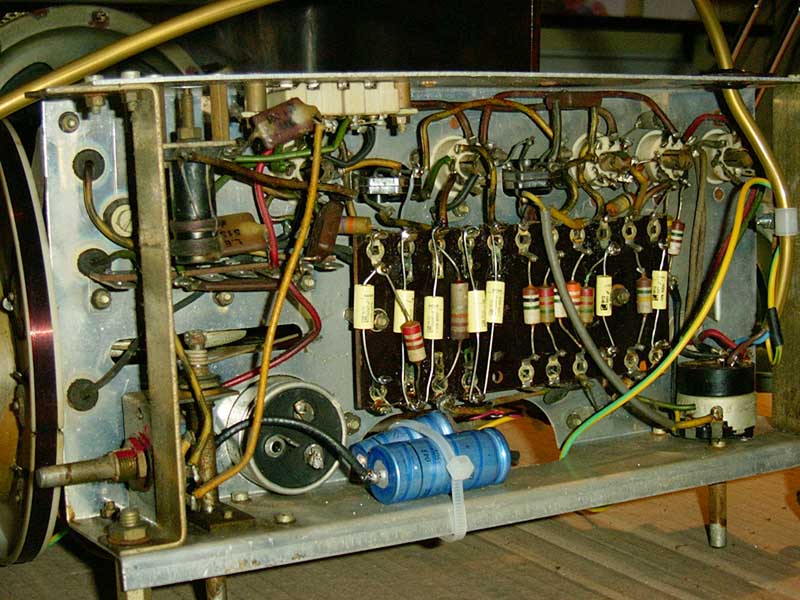
| Starting to replace the capacitors |
The old HT smoothing caps are disconnected, but left in place, and new ones wired in.
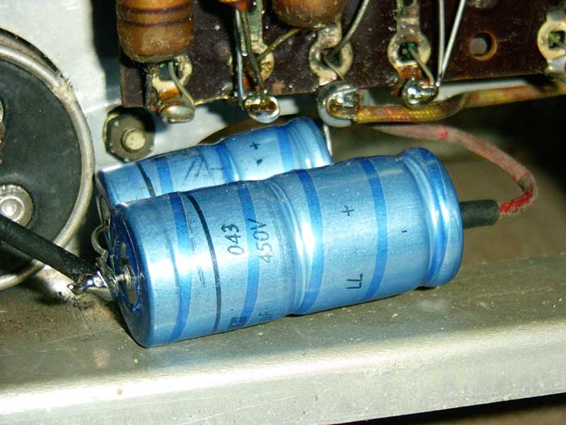
|
| New HT smoothing caps |
The H.T. smoothing capacitors are cable-tied to the chassis.
The valve sockets, volume pot and waveband switch are all given a squirt of Servisol contact cleaner.
Referring to the set's "Trader" circuit diagram, a mains cable is wired to the switch on the volume pot, ensuring that live and neutral are connected the right way round (live to the mains dropper R17, and neutral to the chassis via the scale illuminator bulbs and shunt resistor R18).
The mains plug is fitted with a 1A fuse.
An external speaker is attached.
For added safety at this stage, the radio is powered up through an RCD adaptor.
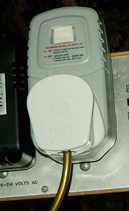
|
| RCD adaptor |
When first powered up, the radio does actually work, but with a loud hum on the audio, irrespective of volume setting. Luckily, a spare, secondhand replacement for the UL41 audio output valve is to hand and when this is plugged in, the radio sounds fine.
Nothing too technical there, then!
|
| It lives! |
The scale illuminator housing is resprayed white using Smoothrite paint.
An attempt to clean the plastic (celluloid?) diffuser with a cleaning solvent ends in disaster as the solvent attacks the material. This is repaired by sanding off the whole surface.
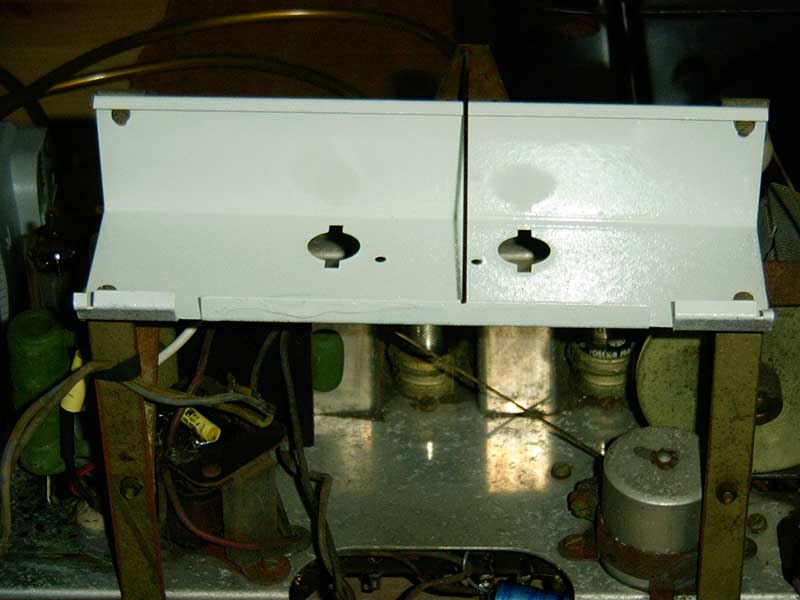
|
| The scale illuminator housing is resprayed white |
|
| The diffuser re-fitted |
Gently pressing on the speaker cone produces a "crunching" sound. Close inspection reveals that the small cloth diaphragm at the rear of the main cone has completely split away, presumably in the damp. Gently pressing it back in place allows the main cone to move freely. Super Glue is used to repair the damage.
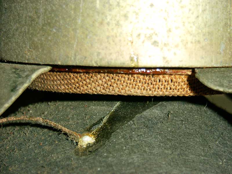
|
| The speaker rear diaphragm has come loose in the damp, and is stuck back with Super Glue |
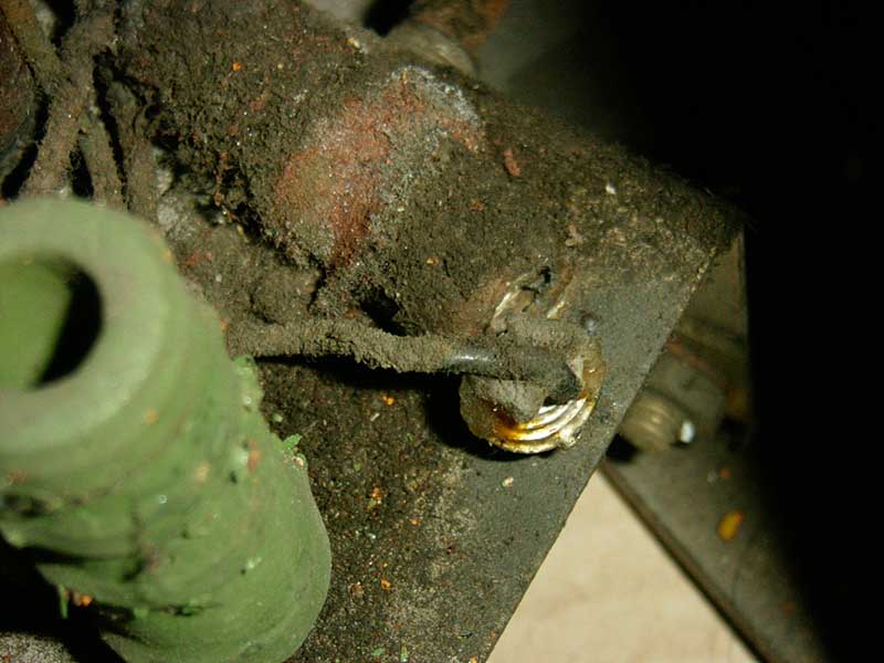
The two brass power input pins are removed to leave as little metalwork as possible exposed externally.
A grommet is fitted, and a 3-core cable passed through it.
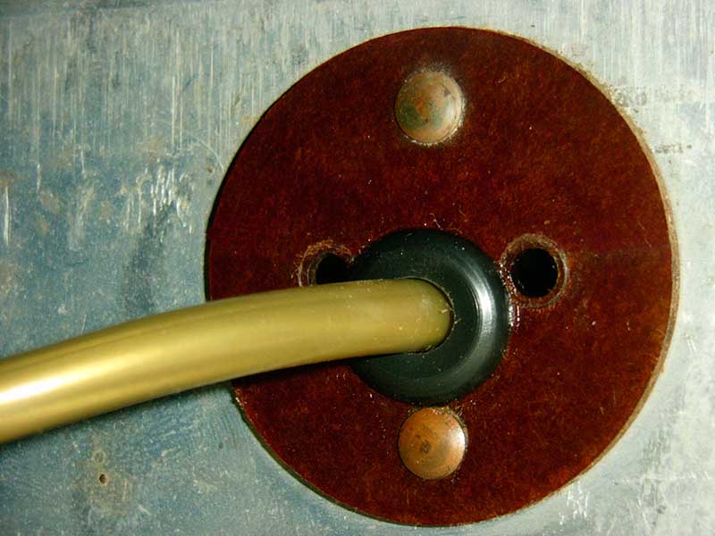
|
| The new cable entry |
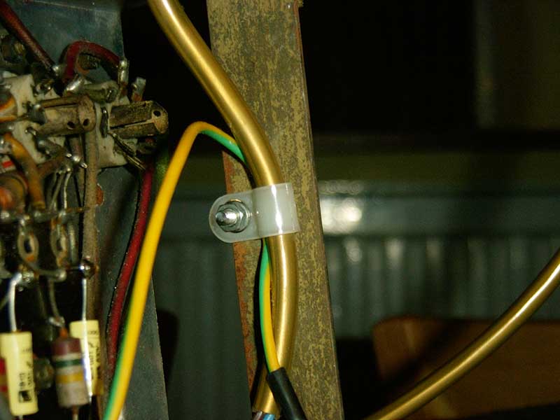
The cable is P-Clipped to the chassis to prevent it from being pulled or twisted.
The earth wire is screwed to the speaker grille to prevent the grille from ever becoming live
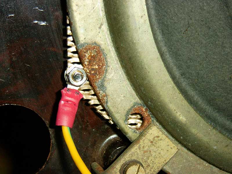
|
| Speaker grill earth connection after re-assembly |
The most satisfying part of the job has to be cleaning up the cabinet.
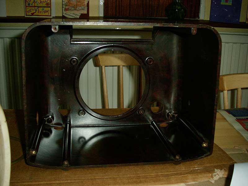
The interior is filthy...
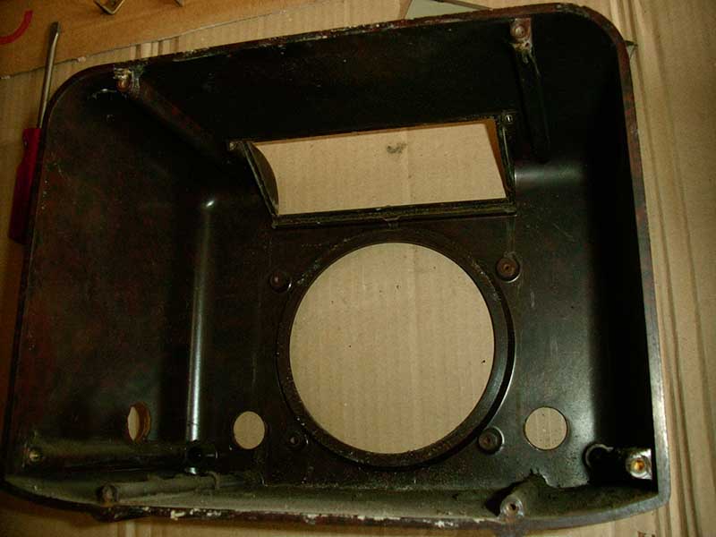
|
| Interior before washing |
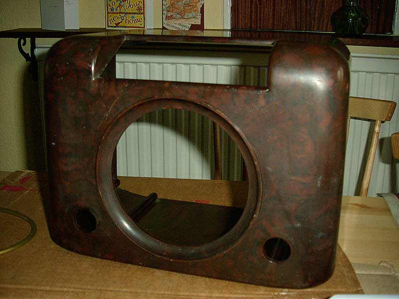
...but after a rinse-out shows its potential.
|
| Interior after washing |
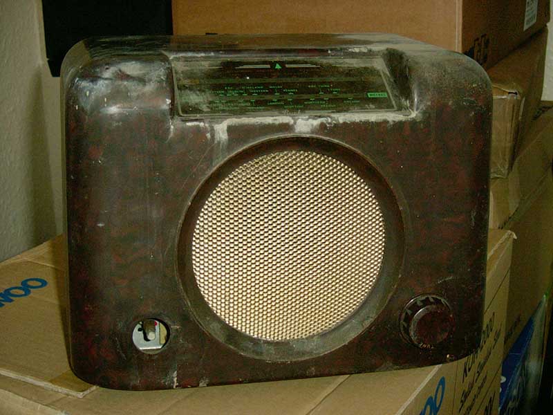
The exterior is dull...
|
| Cabinet exterior |
...but takes a treatment of T-Cut and Colron Finishing Wax well.

|
| The polished exterior |
Finally, the radio is re-assembled...
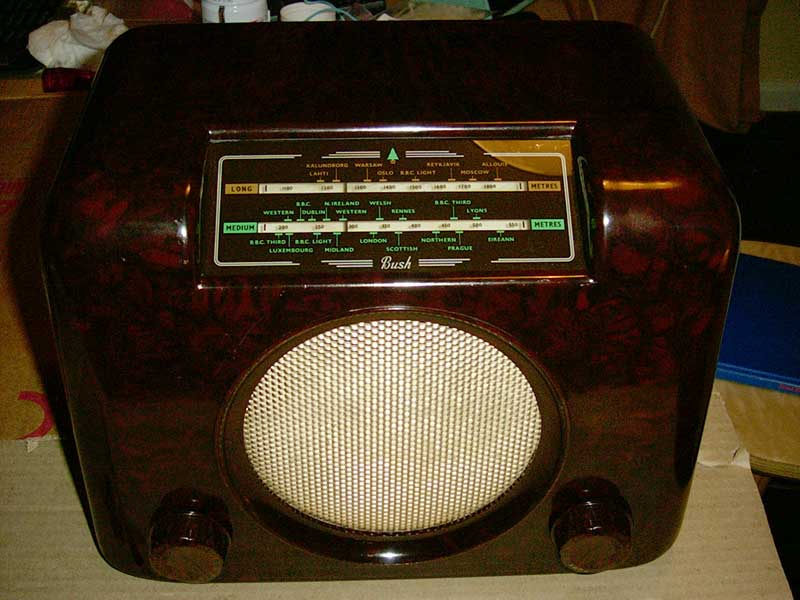
|
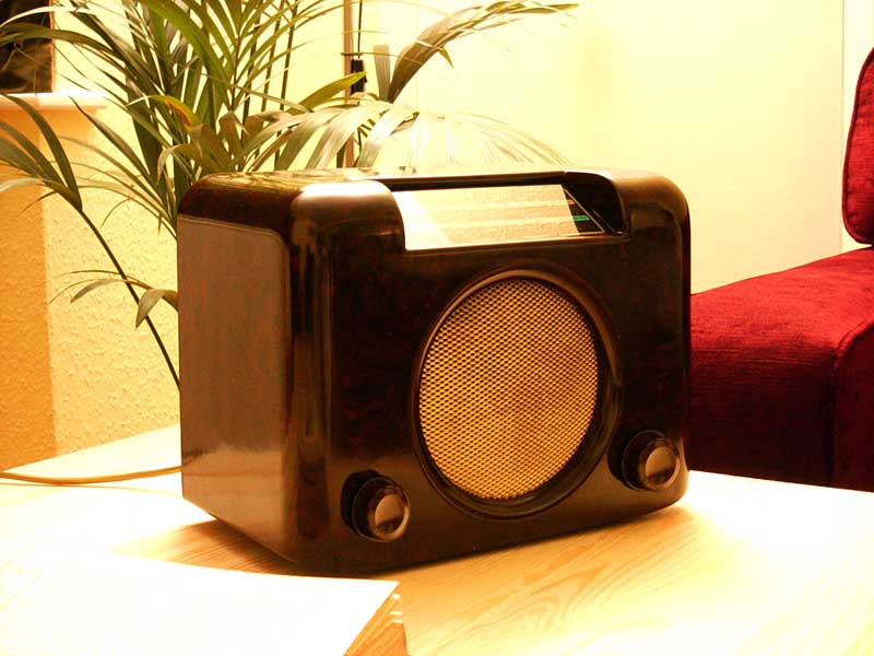
| The completed radio |
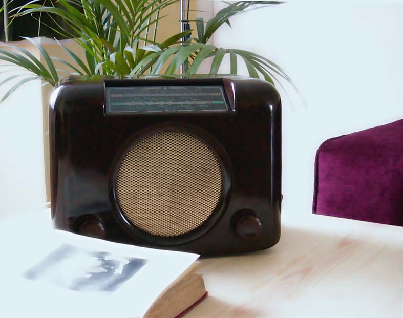
... and takes pride of place in the living room.
Useful links
Radio Renaissance The Wireless Works Paul Stenning's Radio Service Data |